|
Household Electricity Energy Accounting
Intro
After I have got an updated electricity meter from local
dealer it becames possible to build solution for energy
accounting. Brand new meter has LED on the front panel blinking while
some consumers connected to the network. According to information
from the panel, 10.000 flashes stand for 1KWh of energy spent.
Research & Prototyping
Ok, idea is to put light sensor to the front panel of energy meter
and simply count flashes.
Other options are not feasible since box is sealed, no permissions to
connect any third party devices, even there is most
probably RS-485 or CAN interface available.
First of all we have to make sure that idea works. Here is circuit
diagram for the light sensor part:
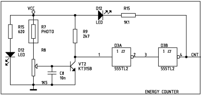
R7 sensor (about 820 Ohm impedance under the light) sticked to
the front panel of energy meter. Then D12 LED flashes when opposite
LED on the meter flashes and sensor detects that. With R8 regulator we need to
tune sensivity to
achieve stable work wich tolerance against background light, so commmon
sence and reasonable compromise help you.
Finally we admit that this part works as a swiss clock.
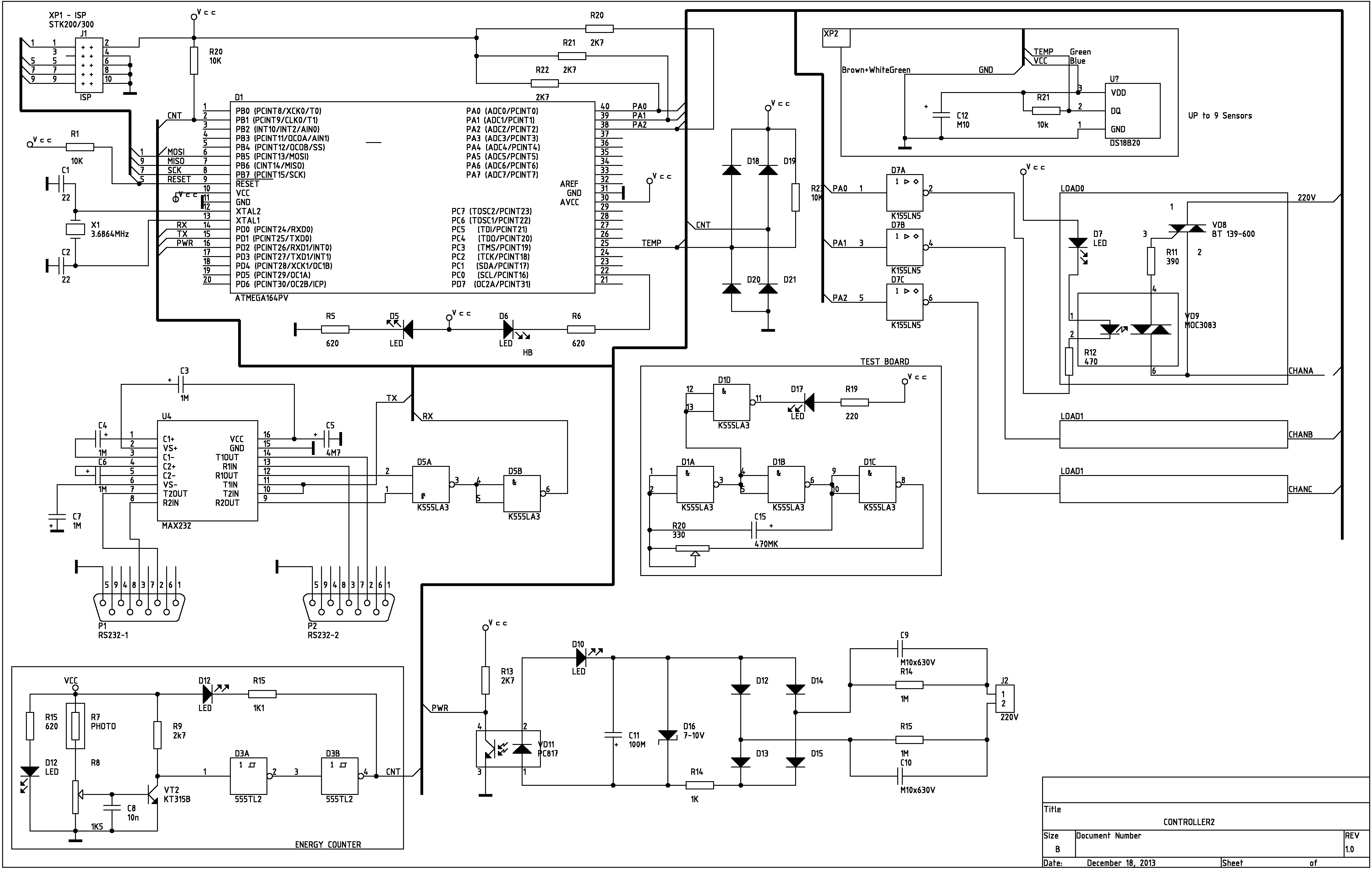
Controller / Accounter
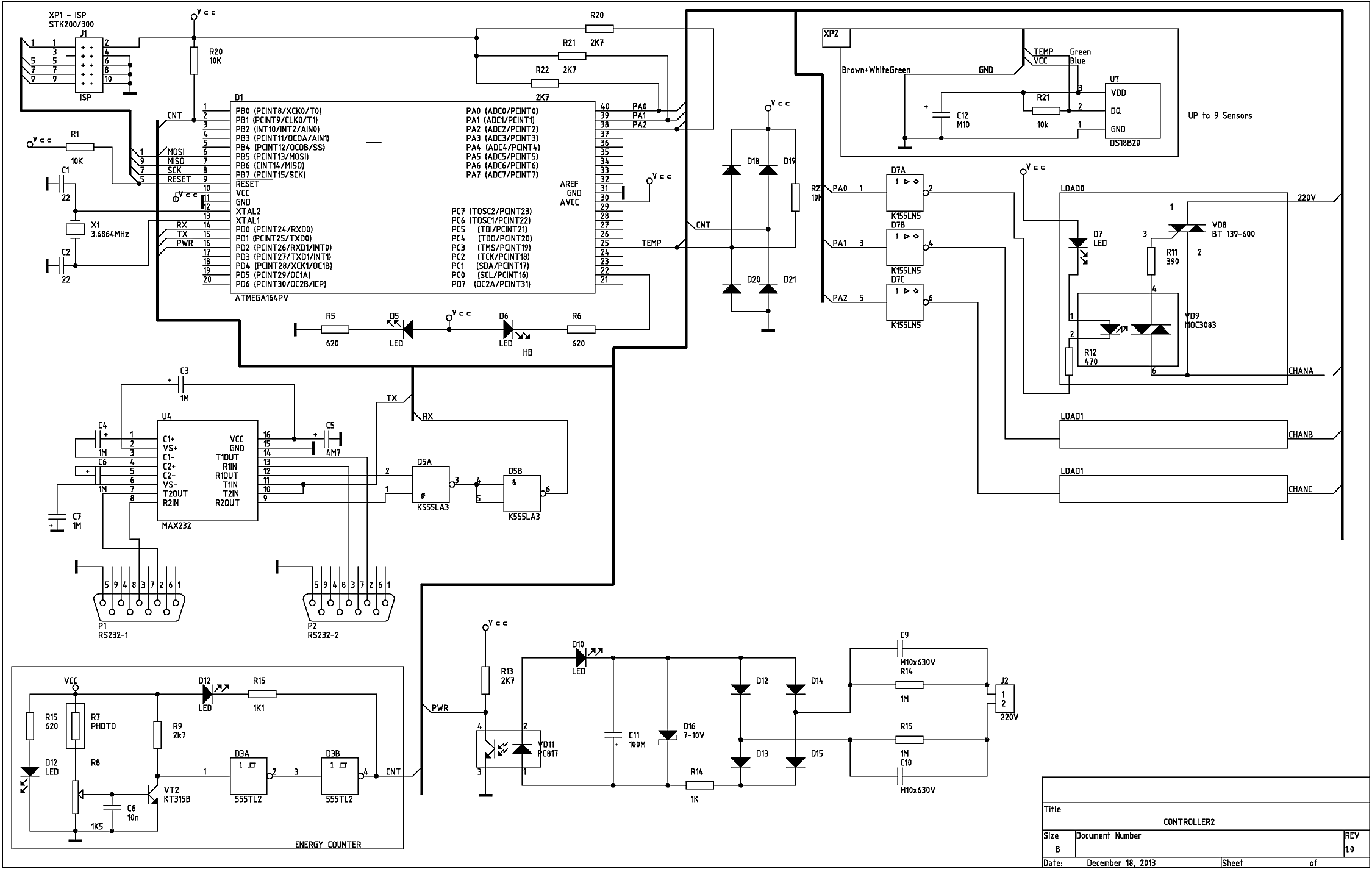
Now it's time to draw full controller diagram. There are some new
features added, such as power monitoring (PWR circuit and related
components), three power control lines (CHAN_A - CHAN_C) and
temperature sensor(s) Dallas DS18B20 (up to 9 sensors supported).
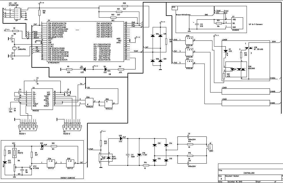
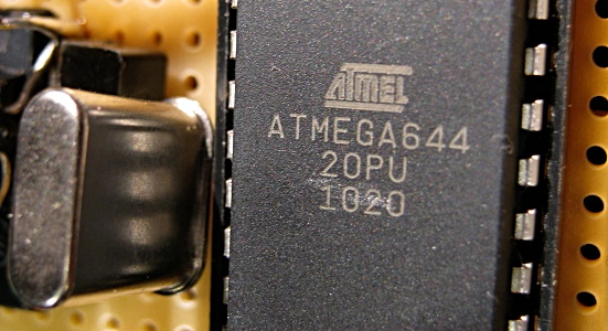
Atmel ATMega AVR is used as microcontroller unit:
Communication with PC done via RS-232 interface, 9600 8N1. There is support for
two simultaneous connections (some tricks with aadditional chip,
unfortunally my
ATMega 644 20PU has one USART only). Circuit from light sensor (CNT) is used
as a clock source for internal ATMega timer. LED D6 indicates activity,
flashing while board is alive. PWR circuit monitors electricity outages.
Three power lines (CHAN_A - CHAN_C) could be used to switch off/on some
devices. Additionally Watch Dog (WD) mode supported with for any of
the above lines.
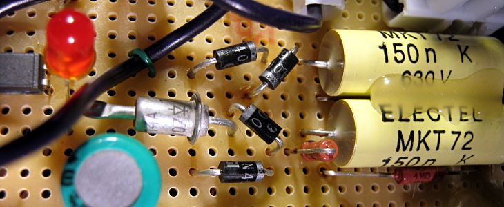
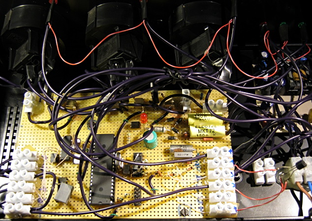
Power Monitoring PWR circuit parts on evaluation board:
The whole controller's inside:
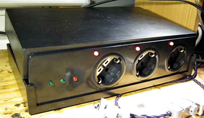
Ready to use device:
Controller command summary (all those are simple one character ones):
| Command |
Purpose |
| '1' |
Search for Dallas DS18B20 sensors connected |
| '2' |
Does search ('1'), then prints temperature for each sensor found |
| 'a' 'b' 'c' |
Does power-off/pause/on for the lines A,B,C correspondingly |
| 'A' 'B' 'C' |
Toggles lines A,B,C on/off correspondingly |
| 'q' 'w' 'e' |
Turns WD mode ON for lines A,B,C |
| 'Q' 'W' 'E' |
Turns WD mode OFF for lines A,B,C |
| 'X' 'Y' 'Z' |
Updates WD Timer values for lines A through C |
| 'k' |
Gets energy counter since, then clears counter |
| 'l' |
Prints current values for all counters (current, total,
persistent stored in EEPROM) |
| 'p' |
Prints average consumption for last 30 s |
| 'T' |
Toggles average energy logging on/off |
| Some debug commands |
'r' |
Reboots controller (ATMega jmp 0) |
| '0' |
Prints marker line |
| 'f' |
Prints some debug info, flags etc |
| 'd' |
Prints counters debug info |
Further Steps
There are many ways to process and represent information, for example
I have used RRDTool graphs for energy consumption:
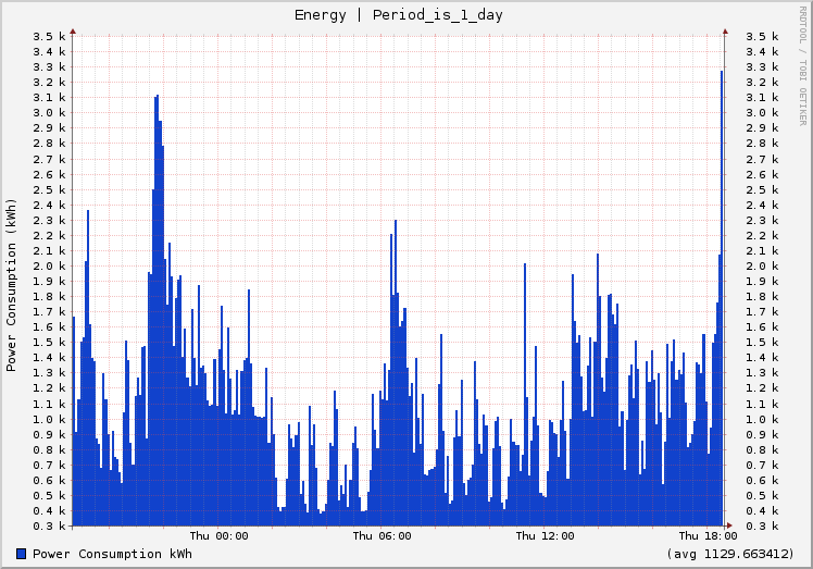
Clearly visible that night energy tariff if not for me ;)
Conclusion
That's all. If I have missed
some issues in my story, feel free to send an email if something is unclear!
Appendix
Tags: avr microcontrollers electronic
Back
|