|
Atmel AVR Watch Dog For ASUS Routers With Alternate Firmware (Oleg's NG firmware, like OpenWRT) And Reliable 3G Modem Dongle HowTo
Intro
Though I put 'OpenWRT' word into the header, this HowTo is about Oleg's
NG firmware, http://code.google.com/p/wl500g/
[2]. This firmware based on original one
from http://oleg.wl500g.info/ [1].
But 'OpenWRT' from the first glance helps you catch up another way
to use custom software with your favorite router.
I had no option to try OpenWRT out since my box model was not supported then.
Oleg's NG firmware (I omit first word and will call it "firmware"
later on) has
few changes in compare with original one, for example, Linux 2.4
kernel was replaced with 2.6 and firmware supports much more ASUS
routers.
That firmware and OpenWRT have a lot of similarities (as well as
differences), but in the most aspects all below is valid for OpenWRT
with minimal changes in mind.
In summary, this HowTo intended for building reliable internet link
with ASUS router box using USB 3G dongle. Simple external Watch Dog (WD) controller
does USB reset and router reset as well if it hangs for some reason.
Preliminary
You need some ASUS router supported by firmware (please refer [2] for
compatibility list). Since 3G dongle uses USB, router model without USB port is
pretty useless.
I have used ASUS RT-N10U with single USB port and 32M RAM, just this one:

Instalation process firmware chewed up in details here [1].
Hope you had enough patience to follow up all the instructions,
succesfully completed all steps and finally have running box with new pretty firmware.
Few things should be done however after upgrade.
Whenever router finds new USB is mounts one to /tmp/mnt/diskN_M, where
N is disk letter and M is partition number. For example my USB flash
mounted like:
/dev/discs/disca/part1 /tmp/mnt/disca_1
|
Out of the box the only ext3 filesystem is supported, but you can
download kernel modules for ext4 for instance.
Packaging expects system mounted as /opt, so type:
# mount /tmp/mnt/disca_1 /opt
|
With ipkg manager you can install additional ipk packages.
Good idea to download all ipk files into /opt/var/ipkg, then tune
ipkg configuration file:
# cat /etc/ipkg.conf
src local file:///opt/var/ipkg
dest root /

# ipkg.sh update
|
Then you need to install minimal suite, at least:
# ipkg.sh install uclibc-opt
# ipkg.sh install cron
# ipkg.sh install perl
|
More additional packages could be installed just like that.
Getting back to mount process of flash or USB hdd.
There could be many USB disks,
but we have to remount properly only system one. Unlike the others,
system partition contains startup file
/etc/init.d/rc.unslung, so modify /tmp/local/sbin/post-mount (assume system
data on the 1st partition):
# cat /tmp/local/sbin/post-mount

#!/bin/sh
# this script runs whenever new USB disk is mounted
file=etc/init.d/rc.unslung # system partition distinguish
flg=/tmp/flash_mounted     # exit if system already in /opt
if test -e ${flg}
 then
 exit 0
fi

# $2 parameter pases to script as directory name, but buggy for some versions,
# so check manually
for p in a b c d
 do
  path=/tmp/mnt/disc${p}_1
  if test -x "${path}/${file}"
   then
    mount ${path} /opt
    /opt/${file} start
    touch ${flg}
    exit 0
  fi
done
exit 0
|
and /tmp/local/sbin/post-boot:
# cat /tmp/local/sbin/post-boot
#!/bin/sh
rm -f /tmp/flash_mounted
|
Save changes:
# flashfs save && flashfs commit && flashfs enable
|
Some tuning for /opt/etc/init.d/S01rc.local:
...
case "$1" in
   start)
        ...
   # some services we don't need
        kill `pidof watchdog` # this process restarts httpd
        kill `pidof vsftpd`
        kill `pidof eapd`
        kill `pidof lld2d`
        kill `pidof p910nd`
        kill `pidof httpd`
        kill `pidof nas`

   # WiFi off if not used
        wl radio off

    # more fresh date until get updated from local NTP
        /opt/bin/date -s "01/01/2014 00:00:00"

    # tune files in /etc
        cp -f /opt/etc/resolv.conf /etc/resolv.conf
        cp -f /opt/etc/ipkg.conf-etc /etc/ipkg.conf
        cat /opt/etc/hosts >> /etc/hosts

    # hope you already made swapfile ?
        swapon /opt/swapfile

    # I forward syslog messages to another host, so
        kill `pidof syslogd`
        syslogd -m 0 -O /tmp/syslog.log -S -l 7 -b 2 -R 192.168.1.1:514 -L
        ...
   stop)
    # turn off swap before reboot
        swapoff /opt/swapfile
        ...
|
3G USB dongle setup with PPP is pretty straightforward for any
Linux. Instructions could be found
here for example.
Ok, now you have ASUS box with new firmware and 3G link up and running.
Keep going
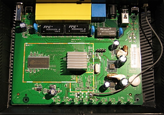
Lets see what inside the router.
Remove four screws on the bottom and box is open easily:
Our goal is RS-232C connector on the board:
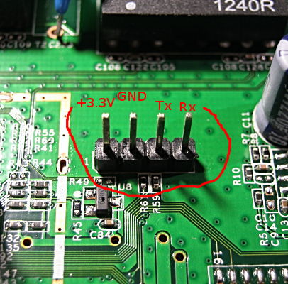
Location, connectior type and pinout can differ
(you can easily find out info for your model), but it is always 3.3V RS-232C.
This connector type and pinout valid for RT-N10U router.
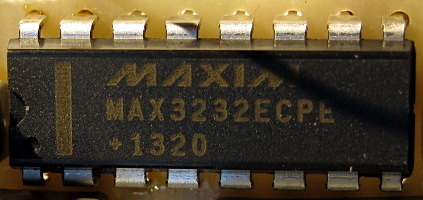
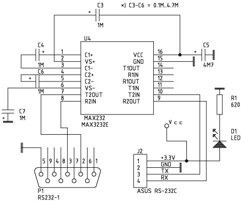
Since RS-232C signal levels are not compatible with PC's interface standard, we have to use converter. For
example this chip is fairly ok for us:
Converter circuit diagram:
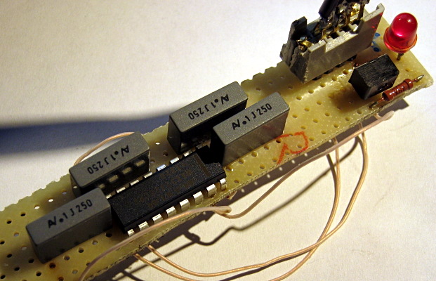
Junk of evalution board plus half an hour of soldering:
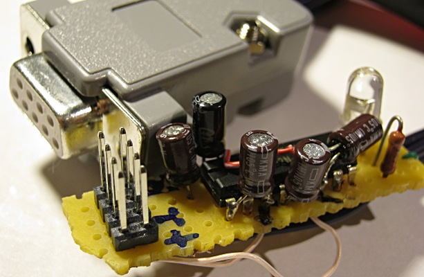
Just another version:
Now it is ok to connect PC to router box:
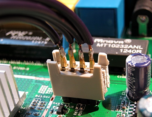
I have used USB/RS-232 PC converter on my desktop. Therefore my tty
device name is /dev/ttyUSB0.
Since router uses 115200 8N1 communication protocol, some setup for PC:
# stty -F /dev/ttyUSB0 115200 cs8
# stty -F /dev/ttyUSB0
speed 115200 baud; line = 0;
-brkint -imaxbel
|
Then start capture RS-232 output:
# cat /dev/ttyUSB0 | tee tty.log
|
And turn on router power. Linux boot messages:
Decompressing...done
CFE version 5.60.127.4 based on BBP 1.0.37 for BCM947XX (32bit,SP,LE)
Build Date: å.. 10æ.. 6 14:20:18 CST 2011 (root@vm-gitserver)
Copyright (C) 2000-2008 Broadcom Corporation.
Init Arena
Init Devs.
Boot partition size = 131072(0x20000)
Found a 8MB ST compatible serial flash
et0: Broadcom BCM47XX 10/100/1000 Mbps Ethernet Controller 5.60.127.4
CPU type 0x19749: 300MHz
Tot mem: 32768 KBytes
...
Loading: TFTP Server.
Failed.
Could not load :: Timeout occured
Loader:raw Filesys:raw Dev:flash0.os File: Options:(null)
Loading: .. 5188 bytes read
Entry at 0x80001000
Closing network.
Starting program at 0x80001000
Linux version 2.6.22.19 (root@localhost) (gcc version 4.6.4 (GCC) ) #1 Sat Apr 27 11:14:03 MSK 2013
CPU revision is: 00019749
Found a 8MB ST compatible serial flash
...
Kernel command line: root=/dev/mtdblock2 noinitrd init=/sbin/init console=ttyS0,115200
...
(full log attached in [4])
|
Last string is very promising since we can try RS-232 out for router acccess.
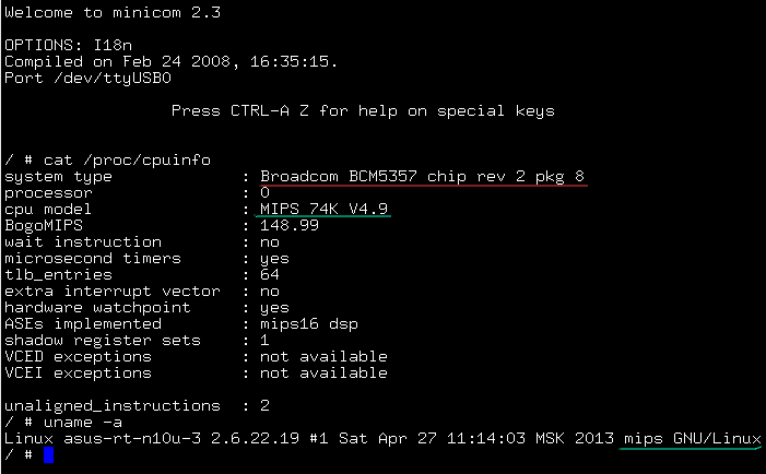
On the PC side minicom terminal program is fine, start it, change port settings:

Then exit to main window, press [Enter] and voila, root access is in the hands:
Watch Dog Controller
Ok, RS-232 is fairly usable now. Hope 3G PPP link still working. Problem
however that most of USB dongles hang occasionally and
unfortunally the only way to continue is plug-off/plug-on procedure.
I have seen some simple solutions using router LED for USB power switching
with (MOS)FET conductors, but strongly oppose this idea.
NOTE, if you play
with USB +5V power only while left Data+ Data- connected with most probably
some signals active it is short way to burn your 3G dongle!
If you examine edge of USB connector, notice the side wires (+5V, GND) are longer, thus
connected first/disconneced last upon plug-on/plug-off.
External WD board with proper USB switching is only the solution I agree with. Since I have
plenty of Atmel AVR chips and experience to deal with, no doubt what kind of
controllers to use. Circuit diagram is here, clickable (printable file
attached [5]):
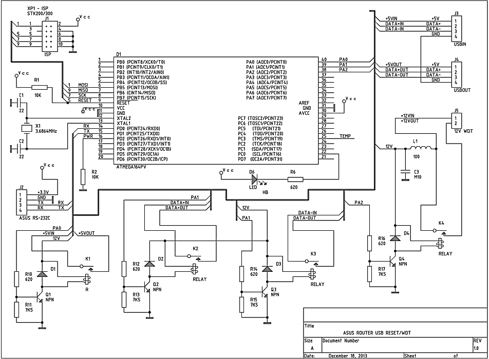
Power +3.3V is coming from router RS-232C connector. +12V power is taken
from the router's input power connector. ATMega 324/644 is a drop-in replacement
for 164. Apparently any ATMega or ATiny could be used (firmware
recompilation required). Relays - any designed for 9-12V voltage with pair of closed
contacts. 3G dongle is connected
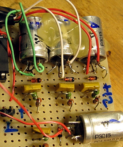
after USB hub. +5V, Data+ and Data- wires are cutted in USB extension
cable ang go through relay K1-K3 (J3-J4). K1 relay switches USB +5V,
K2 and K3 USB Data+ and Data- correspondingly. Relay K4 is connected
in parallel with router power switch and if one is off, controller can
handle router power. Q1-Q4 are any n-p-n transistors
suitable for +12V and relays nominal current.
When controller restarts USB, Data+/Data- wires are disconnected first and
connected only after +5V is connected.
All communication between controller and router is going via
RS-232 port 9600 8N1 protocol. LED indicates operation mode, fast
blinking means waiting
mode and slow one when WD is ready for commnands. The thing is that even RS-232
initial router speed (115200) differs from WD (9600) there is some
junk recieved while box is booting. Right after power-on cycle
controller is waiting until router booting is over and then starts to accept
commands.
In addition it is possible to connect up to 9 Dallas DS18B20
temperature sensors for monitoring (board, room, etc).
Again, piece of evalution board and a some soldering:
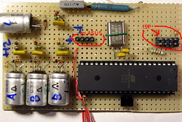
USB extention cable is cutted. +5V, Data+, Data- wires are going via relays.
Controller accepts simple one character commands:
| Command |
Purpose |
| '1' |
Search for Dallas DS18B20 sensors connected |
| '2' |
Does search ('1'), then prints temperature for each sensor found |
| 'a' |
Reconnects USB (in proper order as discussed above) |
| 'c' |
Switches off/pause/on relay K4 (recycle router power) |
| 'A' |
Toggles USB on/off (in proper order as well) |
| 'C' |
Toggles K4 on/off |
| 'e' |
Turns WD Timer ON on (K4 line), timeout is 300s, after timer
expired, K4 line will be switched off/pause/on |
| 'E' |
Turns WD Timer OFF |
| 'Z' |
Updates WD Timer value |
| 'U' |
Toggles WDT update messages, they are turned on after controller restart |
| 'r' |
Reboots controller (ATMega jmp 0) |
| Some debug commands |
| '0' |
Prints marker line |
| 'f' |
Prints some debug info, flags etc |
Log from WD looks like (there is board uptime in the brackets):
LINF [ +0007,12:10:02 ] --- MARK ---
LACK [ +0007,12:10:02 ] WDT on line 3 is On
LACK [ +0007,12:11:02 ] WDT line 3 updated 300 ->360
LACK [ +0008,17:16:15 ] Toggle WDR update logging to Off
LACK [ +0008,17:19:32 ] Toggle WDR update logging to On
# USB reset
LINF [ +0008,18:57:00 ] Line 2 set Off
LINF [ +0008,18:57:00 ] Line 1 set Off
LINF [ +0008,18:57:10 ] Line 1 set On
LINF [ +0008,18:57:10 ] Line 2 set On
# '2' command
LINF [ +0033,23:23:59 ] Looking for DS1820...
LINF [ +0033,23:24:00 ] DS1820, detected devices: 1
LINF [ +0033,23:24:00 ] Device 1 0x267aff00000000ffff
LINF [ +0033,23:24:00 ] Processing DS1820...
LACK [ +0033,23:24:00 ] Temperature 0x267aff00000000ffff 17.00
|
Final Tuning
Small logger which reads router's RS-232 and forwards the messages to
syslog (add rc.tty2syslog.plx launch from S01rc.local):
# cat rc.tty2syslog.plx

#!/opt/bin/perl
use strict;
use Sys::Syslog;
chdir '/';
openlog('ttyS0-logger', 'cons,pid', 'user');
syslog ( 'info', 'Stty port...');
system ("/opt/bin/stty -F /dev/ttyS0 9600 cs8 -hupcl -ixon -ixoff \
 -opost -onlcr -isig -icanon -iexten -echo -igncr -icrnl");
open (TTY, "< /dev/ttyS0") or die "$!";
my $cpid;
if ( !defined ($cpid = fork())  ) {
        syslog('info', 'Cannot fork');
        die "Cannot fork: $!\n";
} elsif ( $cpid ) {
        syslog('info', 'Fork Ok');
        print "Fork Ok\n";
        exit (0);
} else {
        syslog ( 'info', 'Reading tty');
        while (<TTY>) {
                chomp;
                s/\r//isg;
                s/\n//isg;
                next if (/^\s*$/);
                syslog ( 'info', $_);
        }
}
|
Hope you launch 3G PPP link with something like:
/usr/sbin/pppd call provider
|
My version of dongle check script (cron runs it every 5 min):
# cat /opt/etc/cron.5mins/check_modem.sh

#!/bin/sh
logger="/opt/bin/logger -t usb_modem_checker "
grep=/opt/bin/grep
ifconfig=/opt/sbin/ifconfig
wc=/opt/bin/wc
pppd=/usr/sbin/pppd
pppd_cmd="$pppd call provider" # or how you initiate PPP link?
killall=/opt/bin/killall
ping=/bin/ping
echo=/opt/bin/echo
$logger "$0 started"
ifnum=`$ifconfig | $grep ppp | $wc -l`

case "$ifnum" in
   0)
      $logger "PPP iface doesn't exist"
      $killall pppd
      $killall -9 pppd
      $echo -ne 'a' >/dev/ttyS0 # USB reset
      sleep 70 # wait for dongle initialization
      $logger "Running $pppd_cmd"
      $pppd_cmd
      rv=$?
      $logger "Pppd rv is $rv"
      exit 0
      ;;
   *)
esac

# Here we are with link up, however lets check its connectivity
# replace x.x.x.x, y.y.y.y with your ISP primary/secondary DNS servers
$ping -c3 x.x.x.x >/dev/null 2>&1
rv1=$?
$ping -c3 y.y.y.y  >/dev/null 2>&1
rv2=$?

if [ "$rv1" -ne 0 ] && [ "$rv2" -ne 0 ]
then
 $logger "Ping failed"
 $killall pppd
 $killall -9 pppd
 sleep 5
 $logger "Running pppd after ping failover"
 $pppd_cmd
 rv=$?
 $logger "Pppd return status is $rv"
fi
$logger "$0 finished"
exit 0;
|
And additional setup it you use router WD. Add following lines into S01rc.local:
case "$1" in
   start)
...
        /opt/bin/echo -ne 'e' > /dev/ttyS0 # turn WDT on
        /opt/bin/echo -ne 'U' > /dev/ttyS0 # suppress update messages
...
   stop)
...
        /opt/bin/echo -ne 'r' > /dev/ttyS0 # reset controller
...
|
This script will update WDT periodically and if router hangs for some
reason, controller recycles ASUS power:
# cat /opt/etc/cron.1min/wdt_update.sh

#!/bin/sh
/opt/bin/echo -ne "Z" > /dev/ttyS0
|
Conclusion
Ok. Now we done. Thank you for a patience. Probably I have missed
issues in my story, feel free to send an email if something is unclear!
Applications And External Links
Tags: avr microcontrollers electronic asus openwrt
Back
|